Choosing among China’s leading five-axis fiber laser sheet cutting systems takes more than comparing laser power. A capable 5 Axis Fiber Laser Sheet Cutting System must coordinate its cutting head, motion axes, and control software accurately. That coordination affects bevel quality, corner consistency, and performance on complex parts. In practical terms, buyers should examine the machine’s working envelope, supported sheet thickness, positioning accuracy, and cutting-head design. Ask how the supplier validates specifications, and request sample cuts on material similar to your own. Details matter.
This guide introduces ten systems from Chinese manufacturers and compares their stated capabilities, intended applications, automation options, and service support. The list is a starting point, not a universal ranking: a shop cutting stainless steel brackets has different needs from one producing large structural panels. Published specifications can help narrow choices, but they cannot replace a process trial or a clear discussion about maintenance and operator training. Even impressive brochures leave questions. How does the machine behave during long production runs? Are consumables readily available? Those answers deserve careful checking. Some comparisons will remain imperfect because configuration, materials, and local support vary. Readers can use the overview to identify promising candidates, then verify critical claims directly with manufacturers before investing.
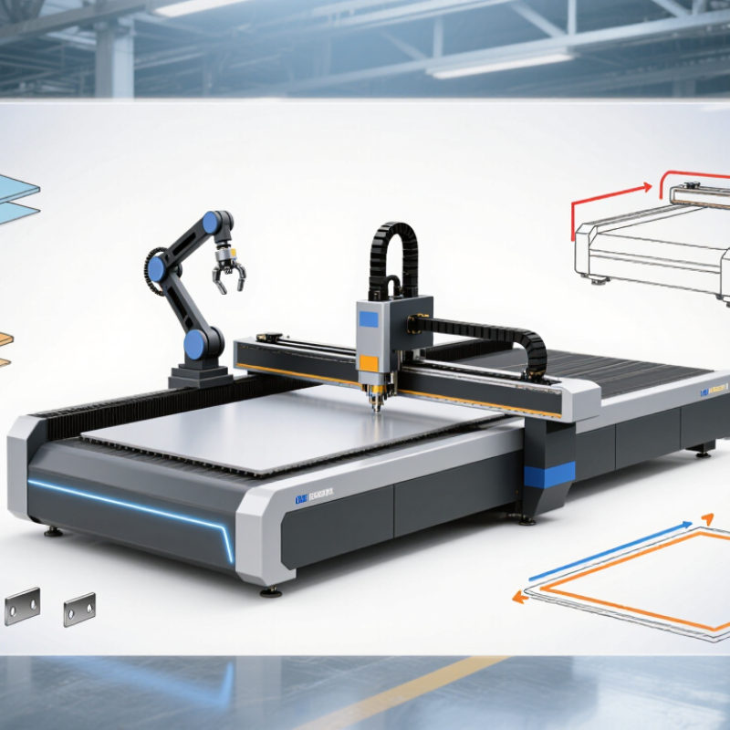
A five-axis fiber laser sheet cutting system moves along three linear axes and two rotary axes. The rotary motion tilts or turns the cutting head, the workpiece, or both, depending on the machine design. This changes the beam angle during a cut. It can produce bevelled edges, angled openings, and three-dimensional contours that a standard flat-bed system may not handle in one setup. That matters.
The system’s value depends on more than its axis count. Sheet thickness, material, part geometry, and required edge quality all affect whether five-axis motion is useful. During setup, operators need to check focus, nozzle clearance, assist-gas flow, and collision paths. A small tilt can change kerf width or leave dross along an edge. The label alone can mislead. Some machines rotate the head; others move the sheet, so their working limits differ. Confirm the usable tilt range, repeatability, and programming workflow against real part drawings. Complex motion can reduce repositioning, but it also adds calibration and inspection work. Not always a faster cut. A sound system is defined by controlled beam orientation, stable motion, and results that match the drawing—not by the number five alone.
A typical five-axis configuration combines three linear motion axes with two rotary or tilting axes. Together, they position the cutting head and adjust its angle for processing angled surfaces and complex contours. Axis layouts can vary by machine.
A five-axis fiber laser system cuts sheet metal by coordinating the beam’s position and angle. X and Y move across the sheet, while Z controls the cutting head’s height. Two additional rotary axes tilt and turn the head. Their exact arrangement varies by machine. The fiber laser focuses energy into a small spot, melting or vaporizing material along a programmed path. Assist gas clears molten metal from the kerf. Small angles matter.
For a straight cut, the head usually stays perpendicular to the sheet. For a bevel, it tilts as the cutting path advances, shaping an edge for later joining or assembly. The controller synchronizes movement, focus height, laser power, speed, and gas flow. A slight mismatch can leave a rough edge or uneven bevel. Operators often check a test cut, then adjust the settings for the material and thickness. In practice, the process sounds cleaner on paper than it feels on the shop floor. No single setting fits every sheet; even surface condition can change the result.
When comparing China’s top 10 five-axis fiber laser sheet cutting systems, start with measurable specifications, not headline wattage. Check working area, axis travel, rotary-head range, positioning accuracy, and repeatability. Ask whether accuracy figures apply across the full sheet or only a small test zone. Small detail, big difference.
Match laser power to your actual materials and thicknesses. Then request sample cuts in the metals and gauges you use, with edge quality and cycle time recorded. ISO 9013:2017 provides a framework for assessing thermal-cut surface quality and dimensional tolerances. It helps make supplier claims more comparable. A polished sample is not a production guarantee.
Automation matters, too. The International Federation of Robotics reported 541,302 industrial robot installations worldwide in 2023 in World Robotics 2024. This is broader than laser cutting, but it shows why loading, unloading, and software integration deserve attention. Compare nesting software, gas consumption, extraction, maintenance access, and local service response. Ask for operating data from a similar job. Numbers need context. I would still verify repeatability over a full shift; one short demo can miss drift, setup time, and material variation.
China’s five-axis fiber laser sheet cutting systems are designed for parts with angled edges, bevels, and complex contours. Their tilting cutting heads can reduce manual repositioning, especially when a job combines flat profiles with sloped cuts. The ten notable systems in this category are best compared by working area, axis travel, laser power, and supported material thickness—not by headline specifications alone.
Look closely at the machine’s cutting head, motion control, and fume extraction. A stable head matters when it moves across a large sheet; even small vibration can affect a bevel’s edge. Ask for sample cuts in the materials and thicknesses your shop actually uses. Check whether the supplier can explain setup, calibration, and routine maintenance in clear terms. A polished demonstration is useful, but it is not a full production test.
Not every shop needs five-axis cutting. It can add programming and operator demands. That is easy to overlook. Compare how each system handles nesting, loading, and changeovers, too. Published speed figures rarely show the whole shift, and real results depend on material quality and process settings. A careful shortlist should balance cut quality, service access, and the work the machine will perform day after day.
Five-axis fiber laser sheet cutting systems are useful when flat profiles need angled edges, bevels, or compound contours. Fabricators may use them for machine frames, transport components, and custom enclosures. On thick material, a tilted head can prepare a weld edge in the same setup, reducing repositioning. Less handling helps. Yet results depend on material, thickness, and a stable cutting recipe; axis count alone proves little. Stainless steel, carbon steel, and aluminum respond differently to power, focus, speed, and assist gas. That detail matters.
Selection should start with real parts, not a brochure specification. Check usable sheet size, head tilt range, Z-axis clearance, positioning accuracy, and permitted workpiece weight. Then test representative coupons, including the tightest corner and steepest bevel. Inspect kerf width, dross, edge angle, and repeatability after the machine warms up. Ask whether the control software supports your CAD/CAM workflow and helps prevent head collisions. Review extraction, guarding, operator training, consumables, and service response too. These are production factors. It is easy to overvalue speed on paper. Some shops may find five axes unnecessary for mostly flat, simple parts. Budget time for trials. Measured cycle times and accepted edge quality show whether the added complexity pays off.
| No. | System Configuration | Typical Laser Power | Typical Working Area | Indicative Material Capability* | 5-Axis Capability | Common Industrial Applications | Key Selection Factors |
|---|---|---|---|---|---|---|---|
| 1 | Compact precision 5-axis sheet system | 1–3 kW | Approx. 1,500 × 3,000 mm | Thin carbon steel and stainless steel, commonly up to about 6–12 mm depending on material and process | XYZ motion with two rotary axes for angled cuts and bevels; travel and tilt limits are model-specific | Electrical cabinets, small enclosures, appliance panels, and precision prototypes | Prioritize positioning accuracy, small-part handling, nesting software, and low-volume flexibility |
| 2 | General-purpose 5-axis sheet system | 3–6 kW | Approx. 1,500 × 3,000 mm | Commonly used for thin-to-medium sheet; practical limits vary substantially by alloy, gas, and cut quality target | Tilting cutting head supports bevels and multi-angle features on flat or formed workpieces | Metal fabrication, machinery covers, commercial equipment, and job shops | Compare daily throughput, cutting-head tilt range, setup time, and service availability |
| 3 | High-speed medium-format system | 6–12 kW | Approx. 2,000 × 4,000 mm | Suitable for a broad range of medium-gauge steel sheet; maximum thickness is process- and quality-dependent | Five-axis contouring for bevel edges, angled holes, and trimming of shaped sheet parts | Construction machinery, transport equipment, and medium-volume fabrication | Check acceleration, axis synchronization, fume extraction, and whether the workload justifies higher power |
| 4 | Large-format high-power system | 12–20 kW | Approx. 2,000 × 6,000 mm | Designed for higher-throughput cutting of medium and thicker sheet; actual limits depend on material and edge requirements | Multi-axis head can cut bevels and features across large panels, subject to head clearance and collision limits | Heavy equipment, ship components, structural fabrication, and large machine frames | Assess foundation, loading method, gas supply, power demand, and material-handling capacity |
| 5 | Bevel-cutting plate and sheet system | 6–20 kW | Approx. 1,500 × 3,000 mm to 2,000 × 6,000 mm | Thickness range depends on required bevel angle, root face, material, and cut quality | Rotary axes enable V, Y, and selected compound bevel geometries; achievable profiles vary by machine | Weld-preparation parts, pressure-equipment components, frames, and heavy fabrication | Confirm bevel accuracy, kerf compensation, programming workflow, and inspection requirements |
| 6 | Formed-sheet and 3D trimming system | 3–12 kW | Work envelope varies; often specified by part dimensions rather than a flat-bed format | Typically processes formed sheet and thin-to-medium sections within the fixture and head-access limits | Five-axis head or coordinated part motion follows three-dimensional contours and trims formed components | Automotive body parts, appliance shells, formed covers, and post-forming edge trimming | Evaluate fixture design, part repeatability, collision simulation, and CAD/CAM support for 3D paths |
| 7 | Tube-and-sheet combination system | 3–12 kW | Sheet area commonly around 1,500 × 3,000 mm; tube capacity is configuration-specific | Sheet and tube capacity must be assessed separately; section shape and wall thickness affect results | Multi-axis cutting head plus rotary tube axis can handle angled cuts and intersecting features | Furniture, frames, fitness equipment, agricultural machinery, and structural assemblies | Check changeover time, chuck range, tube loading, sheet/tube software, and production mix |
| 8 | High-accuracy thin-sheet system | 1–6 kW | Approx. 1,500 × 3,000 mm | Optimized for thin sheet and fine features; performance depends on focus control, gas, and thermal management | Five-axis motion adds angled edges and compound features to precision sheet components | Electronics enclosures, medical equipment housings, instrument panels, and precision parts | Focus on repeatability, small-hole quality, heat input, extraction, and inspection capability |
| 9 | Heavy-duty large-bed system | 12–30 kW | Approx. 2,500 × 8,000 mm or larger, subject to configuration | For thick and large-format workpieces; permissible thickness and edge quality must be confirmed through cutting trials | Multi-axis head provides beveling and angled cutting over large work areas, with clearance constraints | Energy, mining, shipbuilding, rail, and large-scale structural fabrication | Verify bed loading, crane access, thermal stability, assist-gas infrastructure, and operating cost |
| 10 | Automated production-line 5-axis system | 6–20 kW | Typically 1,500 × 3,000 mm to 2,000 × 6,000 mm | Selected to match the production material mix; capability should be validated using representative parts | Five-axis cutting integrated with automated loading, unloading, sorting, or downstream operations | High-volume fabrication, automotive supply chains, appliance production, and contract manufacturing | Compare uptime, automation interfaces, material traceability, safety systems, and total cost per part |
Note: Power, work-area, and material-capability figures are broad industry reference ranges, not guaranteed specifications. Cutting capacity depends on the laser source, machine design, material grade, assist gas, nozzle and focus settings, cut-quality requirements, and operating conditions. Confirm requirements with the machine supplier and representative cutting tests.
It combines three linear axes with two rotary axes. The head, sheet, or both can turn or tilt. This changes the beam angle and can create bevelled edges, angled openings, and three-dimensional contours.
No. Five-axis motion can reduce repositioning, but setup and calibration take time. Not always faster. The part shape and production process matter.
Check working area, axis travel, rotary-head range, positioning accuracy, and repeatability. Ask whether accuracy applies across the full sheet or just a small test area. Small detail, big difference.
Match power to the metals and thicknesses you actually use. Request sample cuts in those materials, with edge quality and cycle time recorded. A polished sample is not a production guarantee.
Check focus, nozzle clearance, assist-gas flow, and collision paths. Even a small tilt can change kerf width or leave dross on an edge.
ISO 9013:2017 offers a framework for assessing thermal-cut surface quality and dimensional tolerances. Use consistent test conditions. Numbers need context.
Compare nesting software, gas use, extraction, maintenance access, and local service response. Ask for operating data from a similar job. A short demo may miss shift-long drift.
Confirm the usable tilt range, repeatability, and programming workflow against real part drawings. I would still test a full shift; one demo can hide setup time and material variation.
A 5 Axis Fiber Laser Sheet Cutting System combines fiber-laser technology with coordinated movement across multiple axes, allowing it to cut sheet materials at varied angles and orientations. This overview explains how the cutting head, workpiece positioning, motion controls, and laser parameters work together to produce complex contours and angled features. It also outlines the specifications that matter when comparing systems, including laser power, working area, axis range, positioning accuracy, cutting speed, automation options, and software compatibility.
The article introduces ten notable types of Chinese five-axis systems and considers their capabilities without focusing on any particular manufacturer. It also explores applications in industries that require intricate sheet-metal parts, such as transportation, machinery, and general fabrication. Selection guidance highlights the importance of matching machine capacity and configuration to material needs, part complexity, production volume, available floor space, operator skills, and long-term service requirements.

+91-79-26840551 / 52 / 53
Domestic: +91 7575 009 654 · Export: +91 7043 505 091
[email protected]
International: [email protected]
Plot No.3, Road No.1, Kathwada GIDC, Kathwada, SP Ring Road, Ahmedabad 382430, Gujarat, India